Mechanical arm electrical interface
1 Electrical interface of manipulator base
1.1 Base introduction
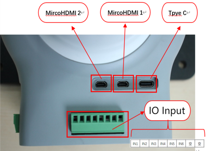
A. The interface, display screen and button on the upper side of the base are shown in Figure 2-3:
B. The interface on the left side of the base is shown in Figure 2-4:
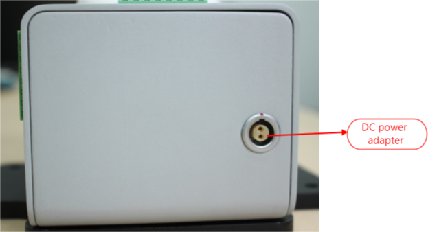
C. The interface on the right side of the base is shown in Figure 2-5:
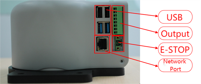
D. The top view interface of the base is shown in Figure 2-6:
1.2 description of base interface
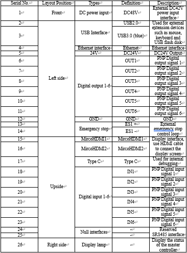
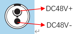
1 DC power input interface:
This interface is connected with the DC48V power adapter interface, and its definition is shown in the following figure:
2 USB2.0 interface:
It is a serial bus standard 2.0 interface for data connection; and users can copy program files using USB interface and can also use the USB ports to connect peripherals such as mouse and keyboard.
3 USB3.0 interface (blue):
It is a serial bus standard 3.0 interface for data connection; and users can copy program files using USB interface and can also use the USB ports to connect peripherals such as mouse and keyboard.
4 Ethernet interface:
It is the port for the network data connection, and users can use Ethernet interface for communication interaction between PC and robot system, also can use it for Ethernet communication with other devices.
5 24V output:
It is internal DC24V and available for user use.
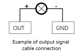
6 Digital input/digital output:
It includes 6 digital input signals and 6 digital output signals, used for interaction with other equipment, which together with other equipment constitute an important part of the automation system.
For example, the user can control the electric gripper mounted on the output flange using a digital output signal or connect it to a PLC for easy signal interaction.
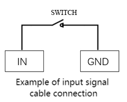
It should be noted that the input/output signal is in the form of PNP, and the following is the schematic diagram of external wiring:
7 Loop terminal of emergency stop:
It is connected with the emergency stop button box and can be used to control the emergency stop of the robot.
Note: the robot must be connected to the emergency stop switch, and ensure that the switch circuit of the emergency stop is connected.
8 MicroHDMI display interface:
Users can connect the MicroHDMI display interface to display the operation page to other device terminals.
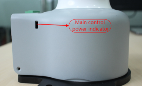
9 Master control display lamp:
It can be used to determine whether the master controller of the robot arm is working properly, and after the robot is powered on, the red light will be on and the yellow light
2 Mechanical arm end electrical interface
2.1 Introduction to manipulator end
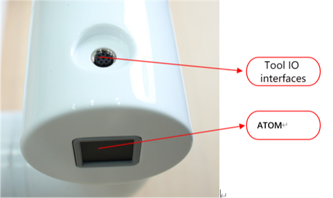
The schematic diagram of the side interface at the end of the manipulator is shown in Figure 2-7:
2.2 End interface description
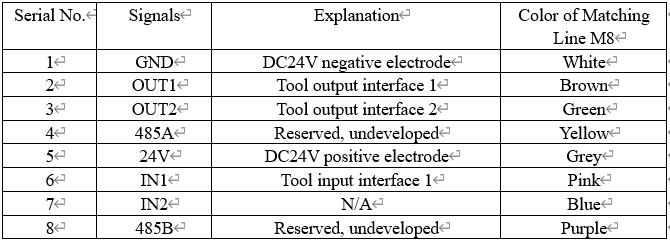
Tool I/O interface:
Here's the tool I/O drawing as shown in the figure, with the Mycobot Pro600 robot providing one input and two outputs.
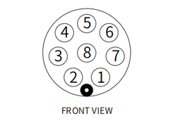
Each tool I/O interface is defined in the following table, and it is noted that the input and output of tool I/ OS are all PNP types and the connection mode is the same as that of the bottom I/O interface.